Module 3.2 — Installation Guide
Installation Prep:
Deployment Planning
The VergeIO Implementation Guide covers the considerations involved in designing and preparing for a VergeIO environment, including hardware selection, network addressing, VLANs, and more.
Networking
Properly configured networks are one of the most important components for a successful installation. It is crucial to know what network a physical NIC will connect to. During the installation process, you will be asked to select and configure your physical networks for each half of the fabric, the external network, and a maintenance network (optional).
Obtaining the server MAC addresses for each port from the switch(es) will help to identify the physical cabling logic.
BIOS
Verify:
- Ensure Virtualization is enabled in the BIOS for all nodes.
- Correct date/time (set reasonably close to actual time) on the first node.
- Virtualization is enabled on all nodes
- All storage adapters and/or RAID cards are set to JBOD
Pre-installation Checklist
Follow the Pre-installation Checklist in the Implementation Guide for more steps/things to check prior to installation.
Installing the Primary Controller Node:
- Boot the first Node (Controller Node) with the VergeIO Install iso (e.g. USB, CD, IPMI ISO redirect, etc.) The standard install will automatically load after a 5 second delay.
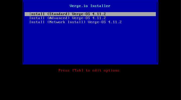
The Advanced install option is intended for use by VergeIO Employees only. Proceed at your own risk!
When the installer begins loading into memory the screen will indicate that VergeOS is installing.
The loading times will vary depending on the medium used to install the OS.
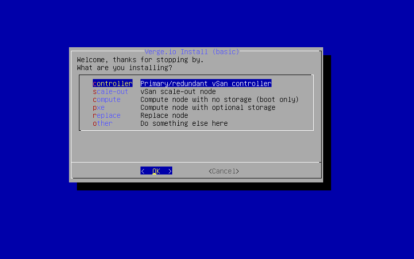
- Select the default option Controller Primary/redundant vSan controller.
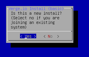
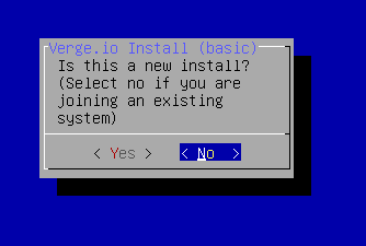
- Select Yes to indicate that this is a new install.
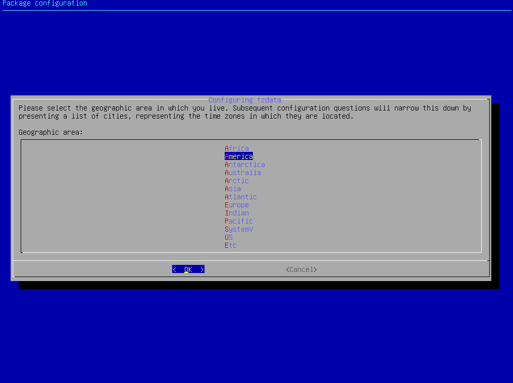
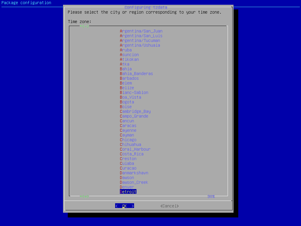
- Choose the Geographic area for the desired timezone.
- Choose the correct City or Region.
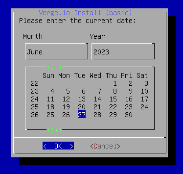
- Adjust the current date and local time if needed.
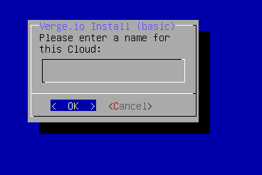
- The Cloud name for a new system defaults to “VergeIO”. The cloud name can be changed here or post-install via system settings.
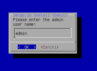
- The Default admin user name for the system root user is “admin”. The name for the system root user can be changed here or post-install by editing the admin user.
- Enter the Password for the “admin” user.
This field cannot be blank and must be at least 8 characters in length.
Make sure to have this password available for the initial login to the installed VergeIO system. The password can be changed post-install by editing the admin user.
Confirm the Password
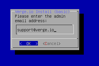
Enter an email address for the admin account.
This email address is used for the default alerting and reporting subscriptions configured for the admin account. This email address can be changed post-install by editing the admin user.
- How many switch networks will you be plugging into?
This shows the number of NICs detected by the OS. It is strongly recommended to keep the number that is originally shown so you can configure ALL detected NICs during the installation (even if not planning to use all of them initially). The following example shows 4 detected NICs.
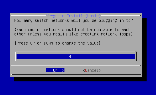
If the External Network ports are to be bonded (LAG), choose one less here (3 in this case).
- A list of all detected NICs is displayed. NICs with an active link will have an asterisk (*) at the beginning of the device description.
- Select the NIC to be used for the first Core Network. The selected device will show an asterisk at the beginning of the line [ * ]. In the below example enp1s1 is the selected NIC. When the correct NIC is selected press [enter].
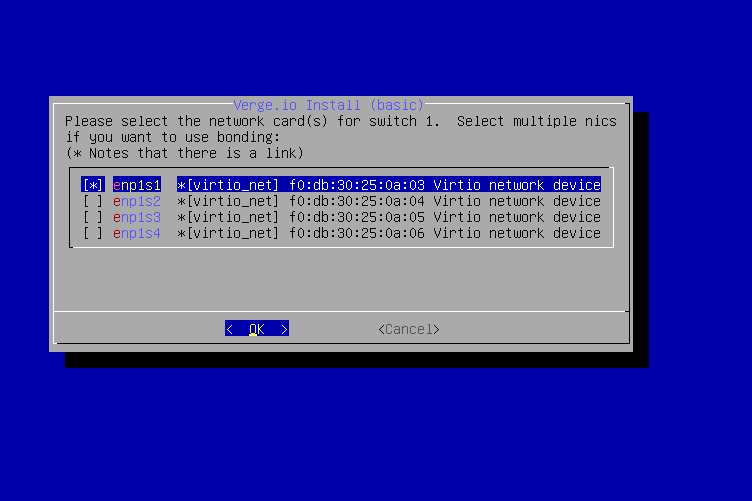
Keyboard Hints:
Use the up/down arrows to move between selections
Use the [Space bar] to select/deselect the highlighted NIC
Do not press [enter] until only the desired NIC contains an asterisk [ * ] at the far left.
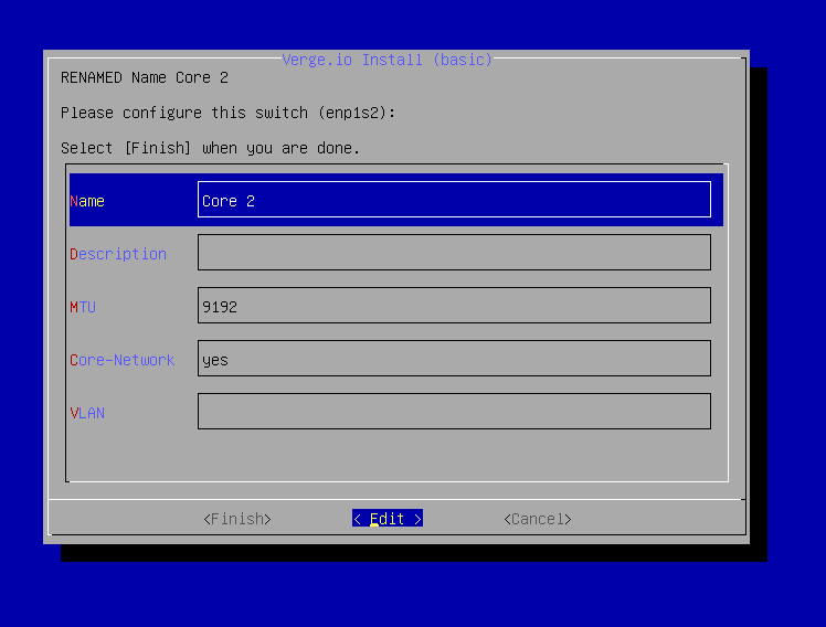
- Configure the First Physical Core Switch.
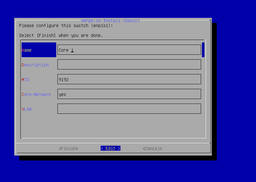
- Name: This designates the name that will be shown in the User Interface
Note: The system will automatically add “Switch” to the name defined. If a name of “Core 1” is entered the system will give the name “Core 1 Switch".
- MTU: The MTU setting must be a value supported by the physical switching hardware and large enough to support the levels of tenancy required. The default MTU is 9192. This setting is compatible with nearly all modern switches and will support 5 levels of nested tenancy.
- Core-Network: Yes indicates that the NIC is designated to be a part of the core network. To remove this designation edit the field and remove "Yes". You can then either type "No" or leave the field blank to remove the designation. In this scenario "Yes" is the correct answer.
- VLAN: If the NICs are designated to be in a tagged VLAN enter the VLAN ID here. In most cases this setting is left blank since the NICs for the core network should be in a Native VLAN or PVID.
- Use [Tab] to select the Finish option and press [enter] once all of the options are completed.
Keyboard Hints:
[Tab] will not move you between fields, but rather moves between the form options(Finish/Edit/Cancel).
[Enter] toggles edit mode on/off. When a field shows a cursor, edit mode is ON and you can modify the contents. When a field is highlighted in blue, edit mode is OFF and you can move between fields with the up/down arrow keys.
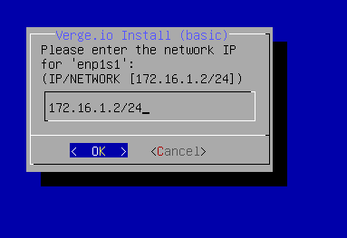
- The network address scheme for the first core NIC defaults to 172.16.1.2/24. In typical use cases the default scheme is ok to use since the NICs should be in a dedicated VLAN preventing them from broadcasting traffic anywhere outside of the environment. If there are any additional questions or concerns consult with VergeIO support for assistance.
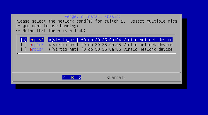
- The remaining unused NICs are now displayed. Select the second NIC that will be used for the Core network and press [enter]. In the below example enp1s2 is selected for the second core NIC.
- Configure the Second Core Physical Switch.
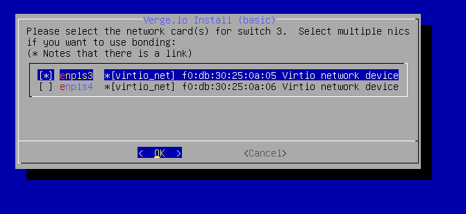
The network address scheme for the first core NIC defaults to 172.16.2.2/24. In typical use cases the default scheme is ok to use since the NICs should be in a dedicated VLAN preventing them from broadcasting traffic anywhere outside of the environment. If there are any additional questions or concerns consult with VergeIO support for assistance.
The remaining unused NICs are now displayed. Select the NIC that will be used for the External network and press [enter].
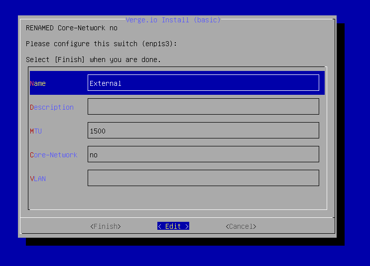
- Configure the External NIC by adjusting the fields with the proper settings (shown below).
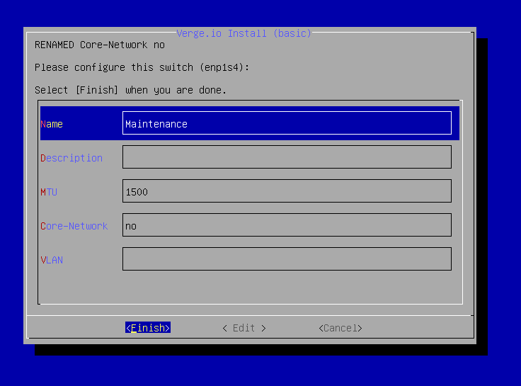
- In the following example the final NIC will be used for the maintenance network. This is an optional feature. The NIC may also be configured in preparation for future use.
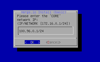
- The default Core VXLAN Network Address is 100.96.0.1/24. In typical cases the IP scheme is left as the default setting. It is designed to run in the Carrier Address space to reduce the potential for conflicts. It is best to consult with VergeIO support for assistance when considering a different IP scheme for core networking.
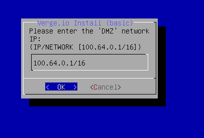
- The default DMZ VXLAN Network Address is 100.64.0.1/16. In typical cases the IP scheme is left as the default setting. It is designed to run in the Carrier Address space to reduce the potential for conflicts. It is best to consult with VergeIO support for assistance when considering a different IP scheme for the DMZ network.
- Select the Switch that you will use for external UI Access (LAN/WAN).
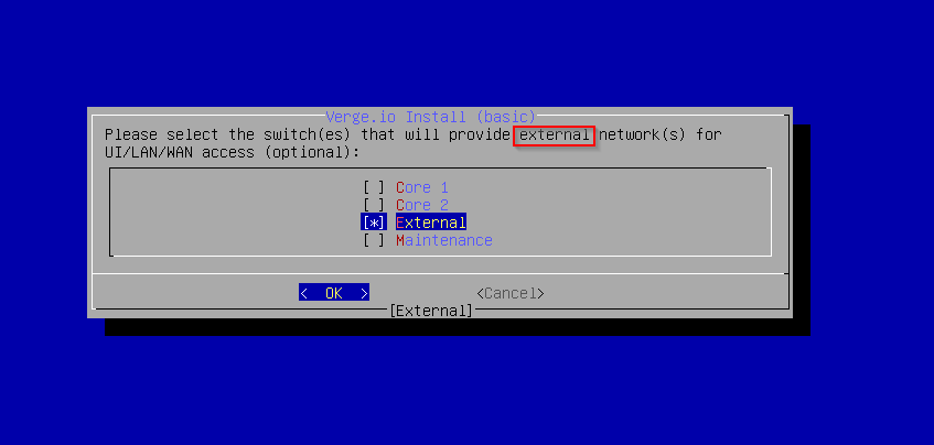
If you do not configure a switch with external UI access, you will only be able to access the VergeIO UI from the local node console until it is configured.
Keyboard Hint:
Use the up/down arrows to move between selections
Use the [spacebar] to select/deselect the highlighted option
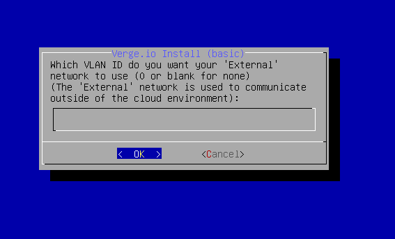
- Enter the VLAN ID for your ‘External’ to use (0 or blank for none). If the external port is setup with a native VLAN this can be left blank.
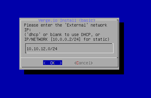
- Enter the network address for the "External" network in CIDR format or leave blank for DHCP.
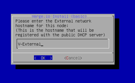
- If using DHCP enter the External network hostname that will register on the dhcp server.
- (Optional) Enter an External Network domain name (auto name resolution.)
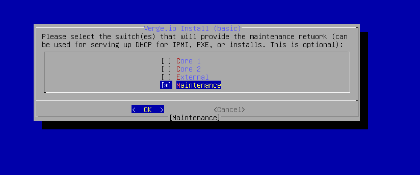
- Select the switch that will provide the maintenance network (optional).
- The maintenance network can provide a PXE install image for installing additional nodes and/or the boot image for drive-less VergeIO nodes.
Keyboard Hint:
Use [spacebar] to toggle item selection
- Enter the username and password for the update server (provided by VergeIO Implementation or VergeIO Sales). Update credentials can also be entered post-install via the settings menu.
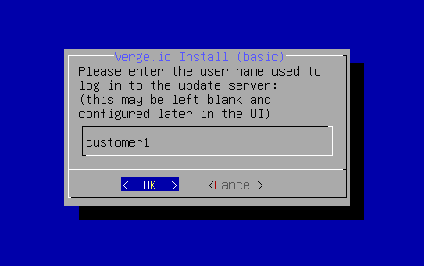
Proper update server credentials are required to start workloads.
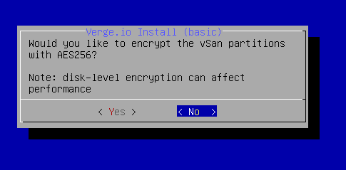
- vSAN Encryption.
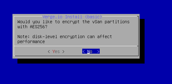
This option is not reversible and cannot be changed without a full re-install. Do not continue until you are certain whether you are encrypting the vSAN or not. Contact your VergeIO Sales Rep or Implementation/Support if you are unsure which option is correct.
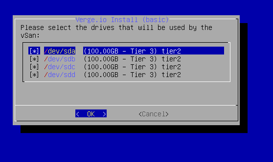
- All detected drives are displayed & selected by default. Unselect any that should be excluded.
Notice that a tier is assigned to each drive. The system will automatically categorize drives to a tier. Tier assignment can be changed per drive in a subsequent dialog.
Make sure to unselect any removable devices or any drives that will be used to store an optional encryption key. 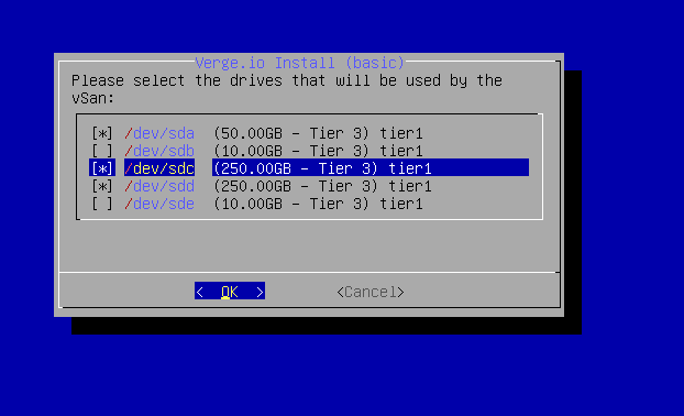
- If all selected drive(s) are in the desired tier(s) (previous screen), press [enter] to proceed. Otherwise press [Tab] to select < Yes > and [enter] to view all drive assignments and optionally change any tier assignments.
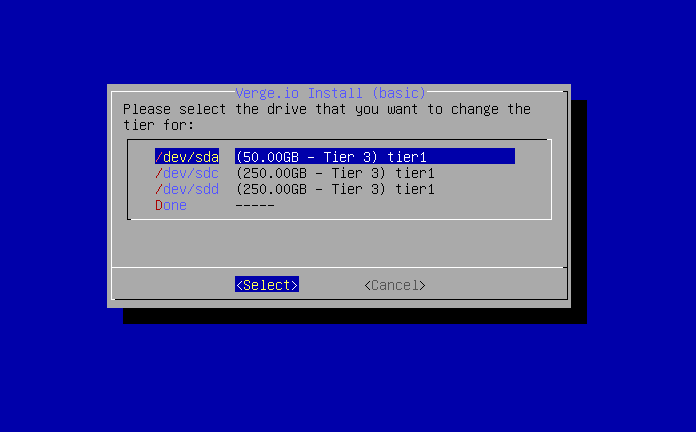
- Changing drive assignments (optional):
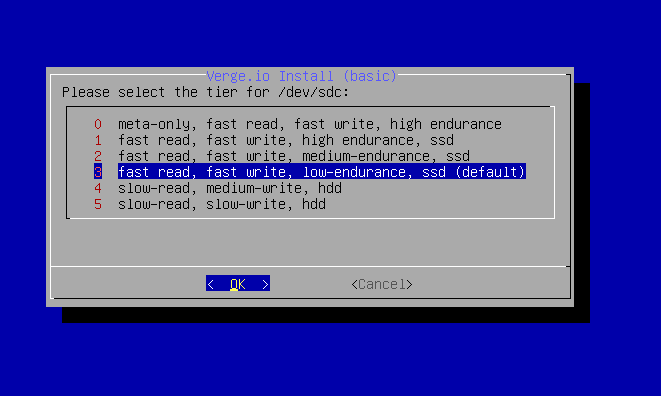
All discovered drives and default tier appointments are now displayed. Select a drive to change and press [enter] to select a different tier assignment for that drive.
All drives in a tier of storage MUST have similar geometry!
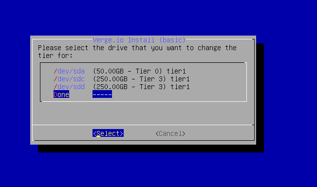
- Repeat the process for each drive that needs to be reassigned to another tier. Once complete, select "Done". Make sure Select is the highlighted item and press [enter].
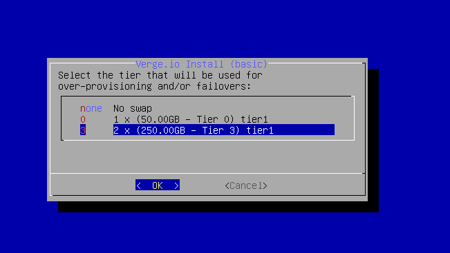
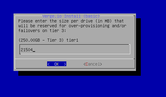
- Configure Swap: There are multiple factors to consider in planning swap including: availability of storage, system use, disk type, etc. Review the VergeIO Implementation Guide or consult with the VergeIO implementation team for further information. The recommendation is to configure enough swap to hold the largest workload expected to run.
- Select the tier to configure SWAP on. In the below example tier 3 has been selected.
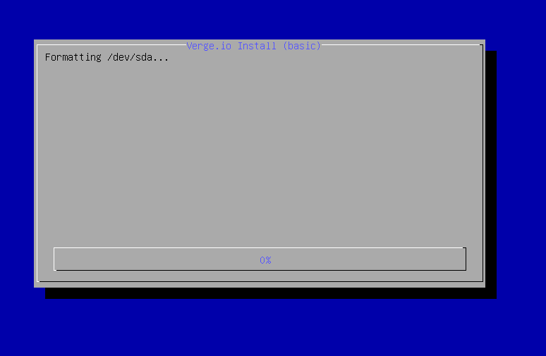
- All applicable drives will now be formatted and added to the vSAN for use.
Drives of larger geometry may take additional time to complete formatting
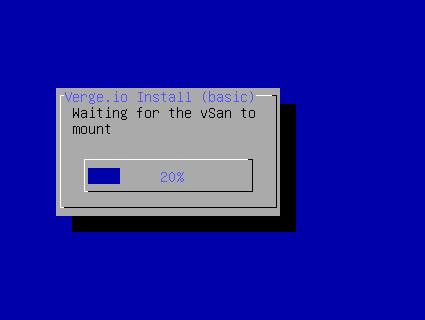
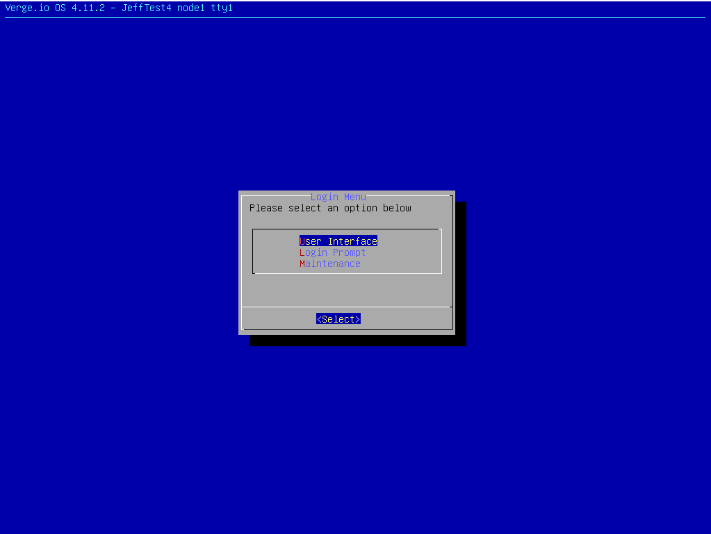
- After the reboot cycle completes the initial menu screen is presented. Once the menu is shown, open a web browser and navigate to the IP address or hostname assigned to the external network to open the user interface.
- Wait for all of the main dashboard lights to show green before installing the next node.
Installing the Second Controller Node:
The second node to be installed will be the secondary controller node. If PXE was configured, you can simply boot PXE install to automatically configure the node with the necessary network settings already configured for Node1. Otherwise, the installer can auto-detect your network setup.
- The second node is the redudant controller. Choose controller Primary/redundant vSAN controller.
- Is this a new Install? Select No to join this node to the previously installed node1.
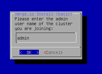
- Enter the appropriate username/password that is already configured for the system (e.g. first node install or what was configured in the VergeIO UI.)
The default username is admin
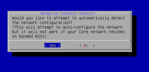
- Would you like to Automatically detect network configuration?
It is highly recommend to always choose Yes. By choosing yes the installer will detect the correct interface for each physical core network, if the NICs are properly cabled and the switch is configured.
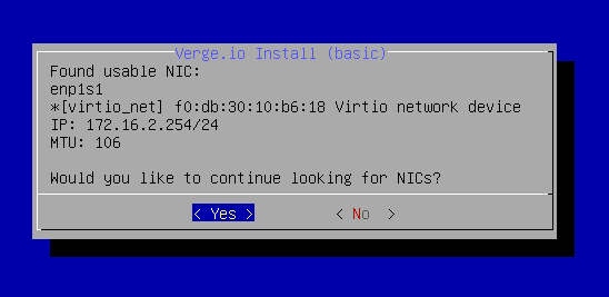
- The installer will auto-detect and configure the physical core network for each interface that is discovered. The "Found usable NIC" pop-up will display each NIC and detect which network it belongs on. Verify that the correct NIC matches the network and MTU. Select "Yes" to continue looking for more NICs if applicable.
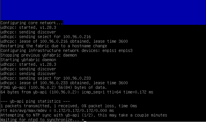
- Next, the system will attempt to obtain a lease on the virtual core network and test its connection. Upon completion, the installer will attempt to sync NTP with the app server running on the live controller node.
- Encryption? Yes/No
Select the same option as selected on the first node.
- Select drives to include in the vSAN. If any extra drives or USB devices show up here, un-check them by pressing the spacebar.
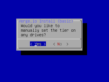
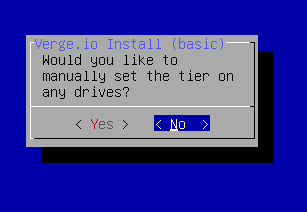
- Would you like to manually set the tier on any drives?
In the previous screen, the default drive tiers were displayed. If that was correct, choose No to skip to the next step. If you would like to change the tier assignments, Choose Yes.
The tier assignments here MUST match with the first node.
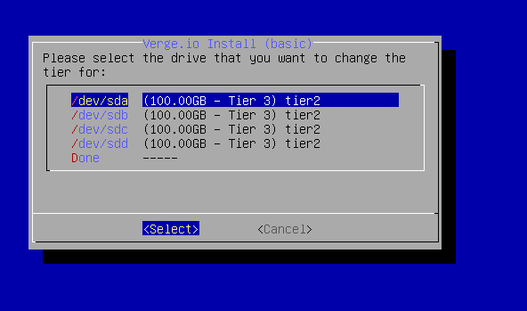
- If you chose Yes to manually set the tiers, you will be able to change the tier for each drive here. Use the arrow keys to navigate to the the drive you want to change to assign the correct tier and press Enter. When complete, arrow down to Done and press Enter.
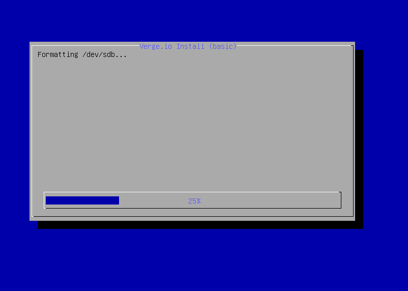
- The installer will begin formatting drives and installing the node.
- The installer will start rebooting the system.
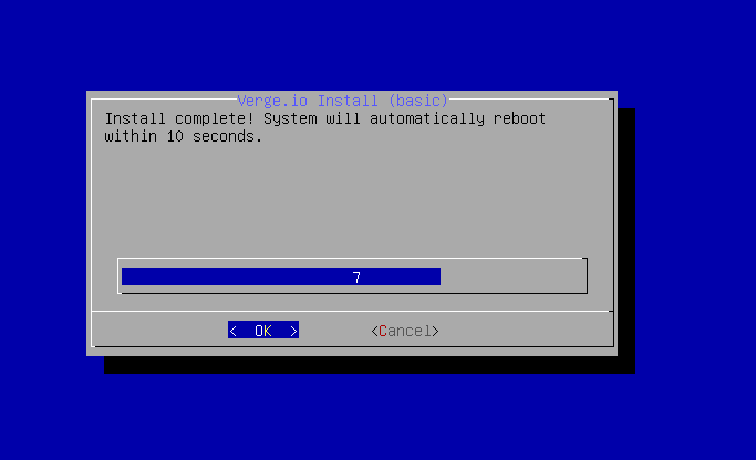
Upon a successful reboot the Verge OS Login Menu will display. You can leave it on this screen and go to the UI IP of the system to verify that this node was added successfully and that there are no errors.
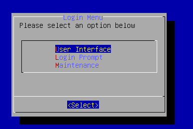
Note: Log entries indicating “root key” errors during the process of adding nodes to a system are normal and can be ignored.
Installing Additional Nodes:
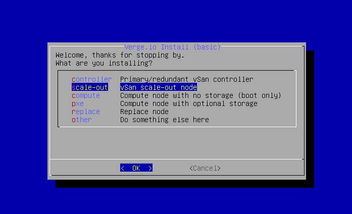
Additional nodes (after the first 2 controller nodes) can be installed as one of the following:
- scale-out - Member node that participates in the vSAN
- compute - Compute only node without vSAN storage (boot only device)
- pxe - Compute node without vSAN storage (no boot device will be present)
NOTE: This is a PXE(Network) boot image of the VergeOS and is not to be confused with the PXE installer.
If you are not performing a scale-out to an existing cluster you MUST add a new cluster in the UI before starting the operation. The installer will ask you which cluster to add the new node to. The steps to completion will vary slightly depending on which options is selected.
Troubleshooting Tips
Cancelling or Restarting a running Install
- Pressing the [Esc] key will cancel the install and bring you to a command prompt
- Type yb-install to resume the install at the same spot
- Type yb-install --restart to start the install over from the beginning